Accurate airflow measurement is essential for HVAC performance, energy efficiency, and system reliability. Traverse measurements—taken across the duct cross-section—help determine average air velocity and overall volumetric flow rate. In this guide, we integrate best practices with references to ASHRAE Standard 111, ASHRAE Standard 62.1, SMACNA guidelines, and ACCA manuals, providing you with a robust technical resource that is SEO optimized for keywords like HVAC airflow measurement, duct traverse measurements, and airflow calculation.
Understanding Traverse Measurements
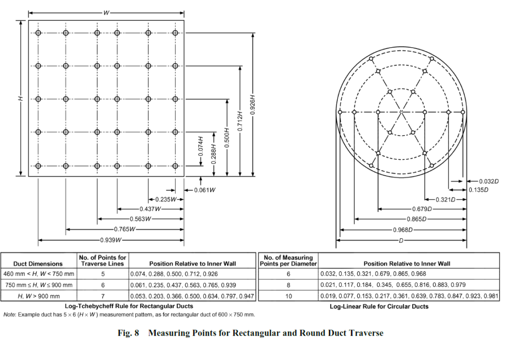
Traverse measurements involve taking multiple velocity readings at different points across the duct’s cross-sectional area. This method addresses the natural variability of airflow by using a grid or predetermined pattern. The technique is well supported by standards such as ASHRAE Standard 111, which outlines recommended practices for accurate airflow measurements.
Key Technical Standards
- ASHRAE Standard 111: Provides guidelines for testing air cleaning devices, including techniques that ensure precise and repeatable airflow measurements.
- ASHRAE Standard 62.1: Focuses on ventilation and indoor air quality, emphasizing accurate airflow measurement for proper system balance.
- SMACNA Duct Construction Standards: Offer recommendations for duct design and installation, helping ensure measurement accuracy in various duct geometries.
- ACCA Manual J and D: Include methods for heating and cooling load calculations and duct design, underscoring the importance of reliable airflow data.
By referring to these standards, HVAC professionals can ensure that their measurement practices comply with industry norms and help optimize system performance.
Why Traverse Measurements Are Critical
Incorporating industry standards into traverse measurement practices ensures that:
- System Performance: The HVAC system delivers the designed airflow necessary for efficient operation.
- Energy Efficiency: Accurate airflow measurements pinpoint imbalances or inefficiencies that might lead to excessive energy use.
- Maintenance and Troubleshooting: Early detection of duct obstructions, leaks, or uneven airflow distribution can be addressed promptly.
- Compliance and Certification: Following SMACNA and ACCA guidelines helps meet local codes and certification requirements.
Essential Tools and Equipment
For accurate traverse measurements, you will need:
- Anemometer/Pitot Tube: A high-precision device for measuring air velocity. Calibration is essential to meet the stringent requirements of ASHRAE and other standards.
- Traverse Template: A guide that marks measurement points on the duct’s cross-section, ensuring consistency as recommended by ASHRAE Standard 111.
- Duct Calculator/Software: Tools to convert the average velocity into a volumetric flow rate, accounting for the duct dimensions per ACCA recommendations.
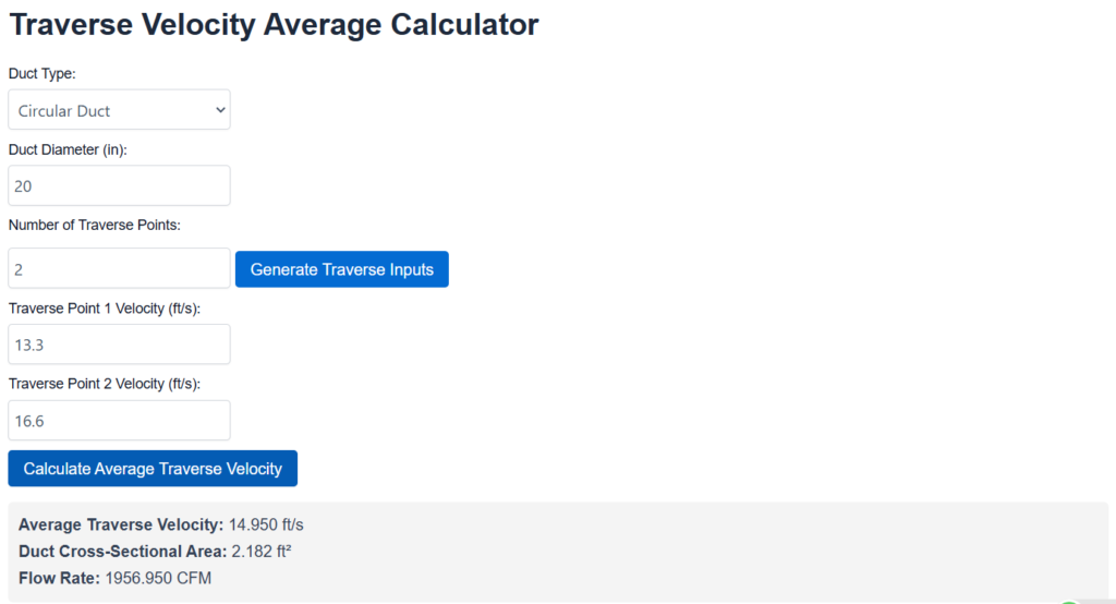
- TheHVACLab Traverse Calculator: Our online tool allows you to input your duct dimensions and velocity readings from each measurement point. This calculator quickly computes the average velocity and total airflow (CFM or m³/h), ensuring accuracy and saving valuable time on manual calculations.
Correct Duct Location: A Critical Consideration
The accuracy of traverse measurements depends not only on the number of measurement points and equipment calibration but also on selecting the proper location in the duct:
- Optimal Location Downstream: Industry best practices recommend taking measurements at least 10 duct diameters downstream from the fan outlet. This distance allows the airflow to become fully developed and stable.
- Avoiding Duct Transitions: Measurements should be taken before any duct transitions, bends, or junctions. A straight-run section of the duct—ideally with a minimum of 5 duct diameters upstream of any transition—helps in capturing a uniform velocity profile.
- Consistent Environment: Selecting a straight and unobstructed section of ductwork minimizes disturbances and provides more reliable data, supporting compliance with ASHRAE Standard 62.1 and SMACNA recommendations.

Step-by-Step Guide to Conducting Traverse Measurements
1. Preparation
- Site Readiness: Ensure the duct is accessible and that the airflow has stabilized. Choose a measurement location at least 10 duct diameters downstream from the fan outlet and before any duct transitions.
- Clean Measurement Area: Remove any debris or obstructions that might affect the readings.
2. Layout of Traverse Points
- Using a Template: Mark measurement points using a traverse template. For circular ducts, a common practice is to use 7–9 points. For rectangular ducts, a grid layout is advisable (see detailed instructions below).
3. Taking the Measurements
- Systematic Readings: At each marked point, insert the anemometer aligned with the airflow direction and record the reading.
- Multiple Readings: In areas with turbulent flow or near duct bends (per SMACNA guidelines), consider additional readings to capture variability.
4. Calculating the Average Velocity
- Averaging Data: Sum the individual velocity readings and divide by the number of points. Use the average velocity along with the duct’s cross-sectional area to calculate volumetric airflow (CFM or m³/h), following ACCA guidelines.
5. Documenting and Reporting
- Record Keeping: Maintain detailed records of all measurements, including any anomalies, for future troubleshooting and to support certification requirements.
Practical Measurement for Rectangular Ducts
Rectangular ducts require a slightly different approach to account for their unique geometry. Here’s how to effectively conduct traverse measurements in rectangular ducts:
- Determine the Measurement Grid:
- Grid Layout: Divide the duct cross-section into a grid. A typical configuration might involve 9 to 12 points arranged in rows and columns. For example, a 3×3 grid is common for smaller ducts, while larger ducts may require more points for an accurate average.
- Edge and Center Focus: Ensure both the center and the perimeter areas are covered since airflow can vary significantly near the walls.
- Template Application:
- Custom Template: Use a template designed for rectangular ducts. The template should clearly mark points along the duct’s width and height, similar in concept to the method recommended by ASHRAE Standard 111 but adapted for a rectangular shape.
- Uniform Spacing: Maintain uniform spacing between measurement points to capture a representative sample of the airflow distribution.
- Measurement Execution:
- Steady Airflow: Wait until the airflow stabilizes before taking readings. Start at one corner and move systematically across the grid.
- Vertical and Horizontal Consideration: Pay attention to both vertical and horizontal airflow variations. Additional measurements near duct corners may capture localized turbulence.
- Data Calculation:
- Average Calculation: Calculate the average velocity from all grid points and multiply by the duct’s total cross-sectional area to determine the volumetric flow rate.
- Comparison with Standards: Verify your calculated results with guidelines provided in ACCA Manual D to ensure compliance with design specifications.
- Documentation:
- Detailed Records: Record each measurement along with its exact grid location. Document any deviations, such as turbulence near corners, which might affect the overall average.
Using TheHVACLab Traverse Calculator
To simplify your airflow measurement calculations, use TheHVACLab Traverse Calculator:
- Input Duct Dimensions: Enter the width and height (for rectangular ducts) or the diameter (for circular ducts).
- Enter Velocity Readings: Input the measured velocities from each designated point.
- Automated Calculations: The calculator computes the average velocity and total airflow (CFM or m³/h) automatically, aligning with industry standards.
- Save Time and Enhance Accuracy: Automating the calculations minimizes human error, ensuring consistent and reliable results.

Best Practices for Reliable Measurements
- Regular Calibration: Ensure instruments are calibrated regularly, as stressed by ASHRAE standards.
- Consistent Methodology: Use a consistent traverse pattern and measurement protocol for valid comparisons over time.
- Stable Conditions: Perform measurements when the system is in a steady state, avoiding the initial transient phase after startup.
- Verify Obstructions: Ensure no temporary obstructions, like maintenance tools, interfere with your measurement points.
Conclusion
Integrating technical standards such as ASHRAE Standard 111, ASHRAE Standard 62.1, SMACNA guidelines, and ACCA manuals into your traverse measurement practices ensures compliance and enhances HVAC system accuracy. Choosing the correct duct location—ideally at least 10 duct diameters downstream from the fan outlet and before any duct transitions—ensures that the data accurately reflects the system’s performance. With practical steps for both circular and rectangular ducts and the convenience of TheHVACLab Traverse Calculator, HVAC professionals can efficiently measure airflow, optimize system performance, and improve energy efficiency.
For more insights and detailed guidance on airflow measurement techniques, be sure to follow our blog at TheHVACLab. We welcome your comments and questions—share your experiences or ask for clarification on any aspect of traverse measurements.
References
1.ASHRAE Fundamentals Handbook 2017 – Chapter-37 (Measurement and Instrument)


