
AHU Evaporator Coil Cleaning: The Silent Energy Drain You Cannot Afford to Ignore
Imagine commissioning a new Air Handling Unit with a design fan static pressure of 800 Pa and a supply airflow of 15,000 m³/h. Three years into operation, the system airflow has quietly fallen to 11,500 m³/h while the fan motor is drawing 18% more current than its design point. Complaints about stuffiness have started coming in from the occupied floors. The chilled water system is running longer hours to compensate. Maintenance has replaced filters twice and the BMS shows no alarms.
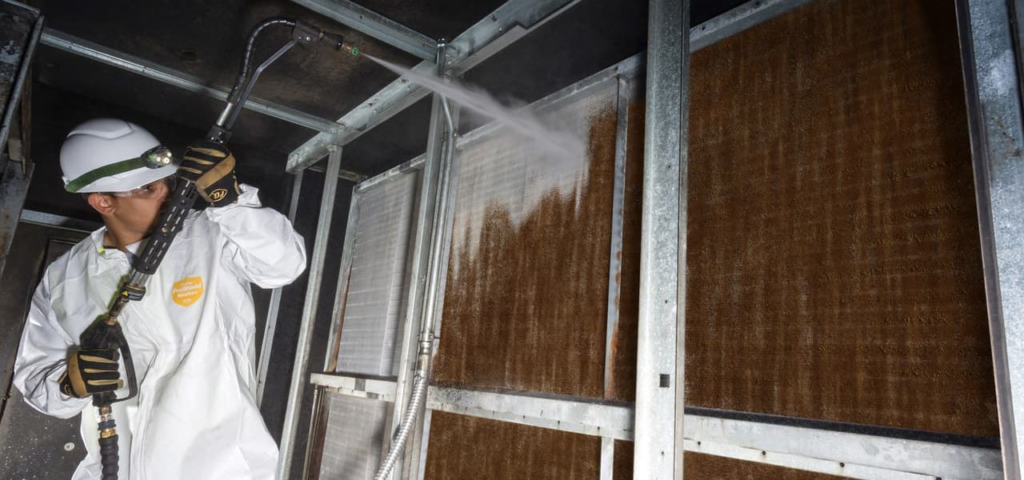
Table of Contents
- Understanding the Evaporator Coil Environment
- What Is Biofouling and Why Cooling Coils Are Particularly Vulnerable
- The Engineering Cascade: Biofouling → Pressure Drop → Airflow Loss → Fan Energy Penalty
- Quantifying the Energy Penalty: A Worked Example
- Comparison: Fouled vs Clean Coil Performance
- Coil Cleaning Methods and When to Use Each
- Recommended Cleaning Frequency by Application
- Common Mistakes in Coil Maintenance Programmes
- Practical Engineering Tips from the Field
- Key Takeaways
- Frequently Asked Questions
- Conclusion
1. Understanding the Evaporator Coil Environment
An AHU evaporator coil more precisely the cooling coil in a chilled water or DX system is a finned-tube heat exchanger where warm, humid return air or outside air gives up heat and moisture to the refrigerant or chilled water flowing inside the tubes. The fins are typically aluminium, the tubes copper or aluminium, and the fin spacing ranges from 8 to 14 fins per inch depending on the application.
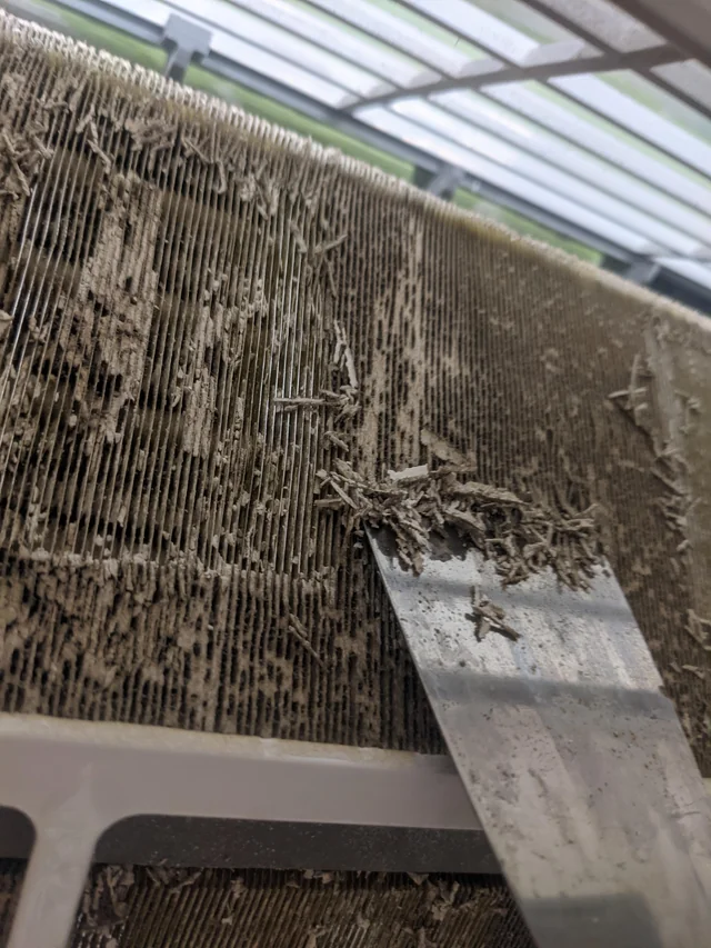
What makes this surface uniquely hospitable to contamination is the combination of persistent surface moisture, moderate temperature (typically 7–16 °C on the air side), and continuous particulate deposition. Every time the coil surface is below the dew point of the incoming air which in most Indian climatic conditions is virtually year-round condensate forms. That thin film of water on the fin surface is a collection medium for airborne particles, dust, fungal spores, and bacteria passing through the upstream filter bank.Even a well-maintained G4 pre-filter does not prevent fine particles below 3–5 μm from reaching the coil face. Over weeks and months, a biological colony establishes itself. This is the starting point of what engineers should classify as air-side biofouling
2. What Is Biofouling and Why Cooling Coils Are Particularly Vulnerable
Definition and Mechanism
Biofouling is the accumulation of microorganisms bacteria, fungi, algae, and the extracellular matrix they secrete (biofilm) on a wetted surface. In HVAC systems, the evaporator coil is among the highest-risk surfaces because it simultaneously satisfies all conditions required for microbial colonisation:
- Sufficient moisture from condensation
- Moderate temperature range (not hot enough to sterilise, not cold enough to inhibit growth)
- Organic nutrient supply from airborne particulates, skin cells, and volatile organic compounds (VOCs)
- Continuous air supply delivering fresh microbial inoculum
Biofilm Formation Stages
Biofilm does not form overnight. The process typically follows four stages:
- Initial reversible adhesion of microorganisms to the wetted fin surface (hours to days)
- Irreversible attachment and early matrix formation (days to weeks)
- Microcolony development three-dimensional structures with embedded water channels (weeks to months)
- Mature biofilm resilient, viscoelastic mat that traps dust, skin cells, pollen, and other debris, forming a dense composite layer
The mature biofilm phase is what creates the engineering problem. Unlike a loose dust cake that can be dislodged by airflow, biofilm is adhesive and mechanically robust. Standard compressed-air blowdown often displaces the outer dust layer while leaving the biological matrix intact on the fin surface.
| Engineering Note: ASHRAE Standard 62.1 (Ventilation for Acceptable Indoor Air Quality) and ASHRAE Guideline 12 (Minimizing the Risk of Legionellosis Associated with Building Water Systems) both highlight wetted cooling surfaces as critical risk points for biological amplification. While Guideline 12 focuses on water-side Legionella, the same first principles of moisture control and surface hygiene apply to air-side biofouling on evaporator coils. |
3. The Engineering Cascade: Biofouling – Pressure Drop – Airflow Loss → Fan Energy Penalty
Step 1 Increased Air-Side Pressure Drop
A clean evaporator coil has a design air-side pressure drop (ΔP) that the manufacturer publishes based on face velocity, fin spacing, and coil depth. For a typical chilled water coil with 8 fins per inch operating at 2.5 m/s face velocity, this is usually in the range of 60 to 100 Pa.
Biofouling combined with the dust trapped within the biofilm matrix progressively narrows the fin passages. The effective free flow area of the coil face decreases. For the same volumetric airflow, the velocity through the remaining open passages must increase, which means the pressure drop rises non-linearly. Research and field measurements consistently show that a fouled coil can exhibit ΔP values 40–100% higher than the clean design condition.
Step 2 Reduction in System Airflow
Most built AHU systems operate on a constant-speed fan with a fixed duty point on the fan curve. When the total system resistance rises due to coil fouling the fan operating point shifts along its characteristic curve toward lower airflow. This is fundamental fan law behaviour.
The result: the supply airflow delivered to the served space falls below design, the ventilation effectiveness deteriorates, thermal comfort is compromised, and in critical applications like hospitals or cleanrooms, pressurisation relationships and outside air fractions may be violated.
Step 3 Elevated Fan Power and Energy Consumption
For a constant-speed fan, operating at a higher system resistance point draws more shaft power for less airflow. This is the counterintuitive but thermodynamically correct reality: the fan motor works harder while delivering less benefit. The fan power is related to the product of airflow and total pressure; in fouled conditions, the pressure term rises disproportionately.
For VAV-controlled fans with VFDs, the BMS will typically command a higher fan speed to maintain duct static pressure setpoint, resulting in elevated energy consumption even though the coil restriction has nothing to do with actual zone demand.
4. Quantifying the Energy Penalty: A Worked Example
Assumption: Single-duct constant volume AHU, chilled water cooling coil. The values below are illustrative and based on typical field conditions; actual results will vary with specific system configuration, fan characteristics, and fouling severity
| Parameter | Clean Coil (Design) | Fouled Coil (Measured) | Difference |
| Coil face velocity | 2.5 m/s | 2.1 m/s (airflow has reduced) | −16% |
| Coil air-side ΔP | 80 Pa | 145 Pa | +65 Pa (+81%) |
| Total system static pressure | 800 Pa | 865 Pa | +65 Pa |
| Supply airflow | 15,000 m³/h | 12,600 m³/h | −2,400 m³/h |
| Fan shaft power (approx.) | 7.2 kW | 8.4 kW | +1.2 kW |
| Annual energy penalty (6,000 hrs) | — | — | +7,200 kWh/year (@6000 hrs) |
| Estimated energy cost (₹8/kWh) | — | — | ₹57,600/year |
These numbers represent a single AHU with a 15,000 m³/h design airflow. A facility with 10 such units a medium-sized commercial office building or a multi-block hospital would be carrying an annual penalty of approximately ₹5.76 lakhs in fan energy alone, not counting the additional chiller energy from degraded heat transfer and extended run hours.
| Real-World Context: During an energy audit of a 250,000 sq ft IT office building in Chennai, three AHUs on the first floor were found operating with evaporator coil pressure drops between 130 and 160 Pa against design values of 75–85 Pa. Post-cleaning measurements (chemical foam wash + high-pressure water rinse) brought all three coils within 5 Pa of design. The quarterly energy savings for the three units combined were estimated at ₹38,000 with a simple payback of under 6 months on the cleaning cost. |
5. Comparison: Fouled vs Clean Coil Performance
| Performance Parameter | Clean Evaporator Coil | Heavily Fouled Coil |
| Air-side pressure drop | At or near design value | 40–100% above design |
| Supply airflow volume | 100% of design | 75–90% of design (CV systems) |
| Fan motor current | At nameplate operating point | 5–20% above operating point |
| Sensible cooling capacity | Full rated capacity | Reduced (lower airflow + fouled surface) |
| Latent cooling / dehumidification | Effective condensate removal | Reduced; biofilm holds moisture |
| IAQ / microbial risk | Low (if regular maintenance) | Elevated biofilm is amplification zone |
| Chiller run hours | At design schedule | Extended to compensate for capacity loss |
| Fan energy consumption | Baseline | 8–25% above baseline (field data) |
| Maintenance cost trajectory | Predictable / planned | Rising reactive + emergency calls |
6. Coil Cleaning Methods and When to Use Each
Method 1 Compressed Air Blowdown
Best for: Light surface dust; dry coil conditions; scheduled quarterly maintenance.
A dry or slightly damp coil is blown down from the downstream (clean air) side toward the upstream face to avoid driving debris deeper into the fin passages. This is a low-cost, rapid intervention but does nothing to address the biological matrix. Treat it as a first-pass between deeper cleans.
Method 2 Low-Pressure Water Flush
Best for: Lightly to moderately fouled coils where the fins are not yet blocked.
Clean water at controlled pressure (typically below 60 bar to avoid fin damage, especially on aluminium fins with corrugated profiles) is applied from the leaving air side, working in line with the fin tubes. Effective for removing loose debris and condensate residue. Not effective for established biofilm.
Method 3 Chemical Foam Cleaning (Coil Cleaner)
Best for: Moderate to heavy biofouling; standard biannual or annual maintenance programme.
An alkaline or neutral pH foam-based coil cleaner is applied to the upstream coil face and allowed to dwell for the manufacturer-specified contact time (typically 5–15 minutes). The foam penetrates fin passages, chemically emulsifies the biofilm and trapped debris, and is then flushed with low-pressure water. For sensitive applications (pharmaceutical, food processing), antimicrobial or EPA-registered biocidal formulations should be specified.
Important: Always verify the coil cleaner pH compatibility with coil fin material. Highly alkaline cleaners can accelerate aluminium fin corrosion over repeated applications. Neutral-pH coil cleaners are preferred for regular programmes on aluminium fin coils.
Method 4 Steam Cleaning
Best for: Severely fouled coils with hardened deposits; applications requiring high-level disinfection (hospitals, pharma).
Low-pressure steam (not dry steam at high temperature, which can damage fins and tube joints) effectively sanitises the coil surface and dislodges tough deposits. Requires careful handling, adequate containment for the condensate runoff, and is generally a specialist contractor activity. Not suitable as a routine method.
Method 5 Ultrasonic Coil Cleaning
Best for: Detailed cleaning during planned maintenance outages; severely blocked coils where water jetting risks fin damage.
Ultrasonic transducers in a cleaning tank create cavitation that dislodges deposits from fin surfaces without mechanical abrasion. Requires coil removal from the AHU casing. Best suited for smaller evaporator sections or when the coil is already being removed for other maintenance.
| Method | Fouling Level Addressed | Relative Cost | IAQ Risk During Cleaning | Recommended Frequency |
| Compressed air blowdown | Light dust | Very Low | Moderate (airborne particulates) | Quarterly |
| Low-pressure water flush | Light–Moderate | Low | Low | Biannual |
| Chemical foam clean | Moderate–Heavy biofouling | Medium | Low (if area isolated) | Annual minimum |
| Steam cleaning | Heavy + hardened deposits | High | Very Low | As needed |
| Ultrasonic cleaning | All levels (off-AHU) | High | Negligible | Major overhaul cycle |
7. Recommended Coil Cleaning Frequency by Application
| Facility Type | Recommended Cleaning Interval | Primary Driver | Preferred Method |
| Commercial offices | Annual (full) + biannual flush | Comfort, IAQ | Chemical foam + water rinse |
| Hospitals (general wards) | Biannual | IAQ, infection control | Chemical foam + disinfectant |
| Hospital critical areas (ICU, OT) | Quarterly inspection + biannual clean | Strict IAQ / pressurisation | Specialist biocidal foam |
| Pharmaceutical cleanrooms | Quarterly + validated protocol | GMP compliance, IAQ | Validated chemical process |
| Data centres | Annual + after any water event | Airflow uniformity, SLA | Chemical foam + dry verification |
| Hotels / hospitality | Biannual | Guest comfort, odour control | Chemical foam + deodoriser |
| Industrial (dusty environments) | Monthly inspection; quarterly clean | High particulate load | Water flush + foam |
| Food processing | Biannual (minimum) | Hygiene, regulatory compliance | Food-safe, NSF-listed coil cleaner |
Note: Frequency recommendations are based on typical operating conditions. Actual intervals should be validated against measured coil pressure drop trends. A delta-P rise of more than 20% above clean design value is a reliable trigger for immediate cleaning regardless of scheduled interval
8. Common Mistakes in Coil Maintenance Programmes
Mistake 1 Cleaning Only the Filter and Ignoring the Coil
Filter replacement is often the only maintenance action tracked in CMMS systems. The coil, located immediately downstream of the filters, accumulates what the filters miss. A facility that replaces pre-filters on schedule but never deep-cleans the coil is managing the symptom while leaving the root problem untouched.
Mistake 2 Cleaning in the Wrong Direction
Blowing or washing from the upstream (dirty) air side toward the leaving air side drives debris deeper into fin passages and can pack it against the tube rows, making it harder to remove and potentially damaging fin structures. Always clean from leaving air side toward entering air side working with the fin geometry, not against it.
Mistake 3 Using Excessive Water Pressure
High-pressure washing (above 100–120 bar) on aluminium fins with tight fin spacings bends, crushes, and closes fin passages permanently. This converts a biofilm problem into a structural one. Fin damage is irreversible without full coil replacement. Always verify the coil manufacturer’s recommendation for maximum safe cleaning pressure before applying water.
Mistake 4 Not Documenting Pre- and Post-Cleaning Pressure Drops
Coil cleaning without measurement is maintenance theatre. Pre- and post-cleaning airside pressure drop measurements (using a differential pressure gauge across the coil section) provide the only objective evidence of cleaning effectiveness and the only basis for optimising cleaning intervals going forward.
Mistake 5 Scheduling by Calendar Rather Than Condition
An annual clean is a starting point, not a fixed rule. A coil in a coastal Indian city with high humidity and airborne salt will foul faster than one in a dry climate. A coil downstream of an inadequately sized G4 filter will foul faster than one with a properly loaded G4 pre-filter and F7 intermediate filter. Condition-based scheduling triggered by measured ΔP is always more rational than a fixed calendar interval.
Mistake 6 Ignoring the Drain Pan During Coil Cleaning
The condensate drain pan beneath the coil accumulates biological growth independently of the coil itself. Biofilm in a stagnant or slow-draining pan can re-inoculate a freshly cleaned coil within weeks. Drain pan cleaning, disinfection, and verification of proper drainage pitch must be integral to every coil cleaning activity.
9. Practical Engineering Tips from the Field
- Establish a baseline: Commission every AHU with a documented coil pressure drop measurement at design airflow. This is the reference against which all future readings are compared. Without a baseline, trending is impossible.
- Install permanent differential pressure taps: Most AHUs do not have coil ΔP measurement ports installed as standard. Adding a pair of static pressure taps one upstream and one downstream of the cooling coil costs very little during installation or the next planned maintenance outage. It pays back in diagnostic clarity for the life of the unit.
- Use a biocidal rinse as a final step: After foam cleaning and water rinse, a final spray of an appropriate biocide (quaternary ammonium compound or hydrogen peroxide-based) applied to the coil face and allowed to dwell briefly before the unit is restarted reduces the re-colonisation rate and extends the inter-cleaning interval.
- Photograph before and after: Visual documentation of fouling severity particularly for healthcare and pharmaceutical clients provides an audit trail, supports FM reporting, and helps justify cleaning budgets to non-technical stakeholders.
- Consider UV-C irradiation for continuous surface disinfection: In critical IAQ applications (hospitals, cleanrooms, and high-occupancy spaces), UV-C germicidal lamps positioned to irradiate the coil surface and drain pan have demonstrated effectiveness in inhibiting biofilm regrowth between cleaning cycles. ASHRAE Position Document on Filtration and Air Cleaning (2018) acknowledges germicidal UV as a supplemental IAQ tool.
- Correlate coil fouling with chiller plant data: A fouled AHU cooling coil reduces heat transfer coefficient and may drive leaving air temperature up, causing the BMS to call for lower chilled water supply temperature. This cascades to lower chiller COP. Monitoring CHWS/CHWR delta-T alongside AHU coil ΔP gives a system-wide energy picture.
10. Key Takeaways
- AHU evaporator coils are persistently wetted surfaces that are inherently susceptible to biofouling due to condensate, moderate temperature, and continuous particulate deposition.
- Biofilm development is progressive and cumulative. The mature biofilm matrix traps dust and debris to form a composite fouling layer that significantly narrows fin passages.
- The direct engineering consequence is increased air-side pressure drop typically 40–100% above clean design values in heavily fouled coils.
- Increased ΔP shifts the fan operating point, reducing supply airflow and increasing fan power simultaneously the worst possible combination for energy efficiency.
- Fan energy penalties from coil fouling are real and measurable: field data typically shows 8–25% above baseline fan energy in severely fouled conditions.
- Chemical foam cleaning is the most practical and cost-effective method for established biofouling; always follow with a biocidal rinse and document pre/post pressure drop.
- Cleaning frequency should be condition-based, not calendar-based, using measured coil ΔP as the trigger metric.
- Drain pan cleaning and disinfection must accompany every coil cleaning activity to prevent re-inoculation.
- Simple payback on a structured coil cleaning programme is typically 3–8 months making it one of the highest-ROI maintenance investments available to facility managers.
11. Frequently Asked Questions
Q1. How do I know if my AHU evaporator coil needs cleaning?
The most reliable indicator is a measured increase in air-side pressure drop across the coil section. A rise of 15–20% or more above the clean baseline, or visible biological growth on the coil face during inspection, are reliable triggers. Reduced supply airflow at constant fan speed and increased fan motor current are secondary indicators.
Q2. How often should AHU evaporator coils be cleaned?
For most commercial buildings, a minimum of one chemical foam clean per year combined with a biannual water flush is a practical starting point. Hospitals, pharmaceutical facilities, and food processing plants should clean more frequently at least biannually, with critical areas quarterly. In all cases, actual cleaning intervals should be validated against measured ΔP trends.
Q3. Can I clean the AHU coil while the unit is in operation?
No. Coil cleaning particularly chemical foam applications requires the AHU to be shut down and isolated. Operating the fan during foam dwell time would draw chemical aerosols into the occupied space. Always follow a lockout/tagout procedure and ensure adequate drainage containment before cleaning.
Q4. What chemicals are safe for aluminium fin coils?
Neutral pH (pH 6.5–8.5) coil cleaners are the safest choice for repeated use on aluminium fins. Strongly alkaline cleaners (pH > 10) can cause galvanic and chemical corrosion over multiple applications. Always check the manufacturer’s data sheet for compatibility. For pharmaceutical applications, use only validated, regulatory-compliant formulations.
Q5. Does a fouled coil also affect indoor air quality?
Yes, significantly. Biofilm on the coil surface is a reservoir for bacteria, fungi (including Aspergillus and Cladosporium species), and microbial volatile organic compounds (MVOCs). Airflow across the fouled coil surface can re-entrain biological material into the supply air stream, degrading IAQ and potentially triggering respiratory issues in sensitive occupants.
Q6. How much energy can I recover by cleaning a fouled AHU coil?
Based on typical field data, a moderately to heavily fouled coil (ΔP 50–80 Pa above design) in a constant-volume AHU system will show fan energy savings of 8–20% post-cleaning. For a 7.5 kW fan motor running 6,000 hours per year at ₹8/kWh, a 15% saving amounts to approximately ₹54,000 per year per AHU.
Q7. What is the difference between biofouling and dust fouling?
Dust fouling is the mechanical accumulation of inert particulate matter in fin passages. Biofouling is the growth of living microorganisms (bacteria, fungi, algae) and the extracellular biofilm they secrete. The two co-exist and reinforce each other biofilm acts as a biological adhesive that traps dust, while dust provides nutrients for further microbial growth. Dust alone can often be removed with water flushing; biofilm requires chemical or disinfectant treatment.
Q8. Can UV-C lights replace regular coil cleaning?
No. UV-C germicidal irradiation is a supplemental tool that inhibits surface biological growth and slows biofilm formation. It does not remove accumulated dust or debris, does not dissolve established biofilm, and does not address coil passages that are geometrically shielded from UV exposure. UV-C is most valuable as a maintenance interval extender, not a cleaning replacement.
Q9. Should the drain pan be cleaned at the same time as the coil?
Yes, without exception. The drain pan is a primary site for biological growth and is directly connected to the coil environment. A cleaned coil combined with a contaminated drain pan will begin re-fouling within weeks. Drain pan cleaning, biocide application, and drainage verification are integral steps, not optional additions.
Q10. Is coil cleaning part of BEE energy audit requirements in India?
The Bureau of Energy Efficiency (BEE) framework for energy auditing in commercial buildings includes HVAC system assessment as a core component. While BEE does not mandate specific coil cleaning intervals, an energy auditor performing a detailed audit (as per BEE Certified Energy Auditor standards) would assess air-side coil condition, measure coil pressure drop, and flag fouling as an energy efficiency opportunity with quantified savings potential.
12. Conclusion
Evaporator coil biofouling is not a niche maintenance issue it is a systemic energy and IAQ problem that affects virtually every AHU in humid climates like India. The engineering chain from biofilm formation to increased pressure drop to reduced airflow to elevated fan energy consumption is direct, measurable, and entirely preventable.
What makes coil fouling particularly insidious is that it develops gradually, without BMS alarms, and is rarely attributed correctly until an energy auditor or a commissioning engineer measures coil ΔP and compares it to the design baseline. By that point, the facility has often spent years paying an unnecessary energy penalty.
The solution is not expensive. A structured coil cleaning programme grounded in condition-based scheduling, the right cleaning chemistry, proper technique, and documented pre/post measurements typically delivers simple payback in under a year. In an industry that often searches for complex solutions to complex problems, evaporator coil cleaning remains one of the simplest, highest-ROI actions available to any facility manager or energy auditor.
If you are responsible for an AHU-served facility and have never measured your evaporator coil air-side pressure drop, that measurement is the right place to start.
| Need an AHU Performance Assessment?TheHVACLab Energy Solutions provides on-site AHU audits that include evaporator coil condition assessment, air-side pressure drop measurement, fan energy benchmarking, and a detailed corrective action plan with quantified savings. Serving commercial, healthcare, pharma, and industrial facilities across India. thehvaclabtech@gmail.com | www.thehvaclab.com |

